Notice the rider
Night, poor weather and competing lights make visibility a critical research topic.
 D8SIGN.STUDIO
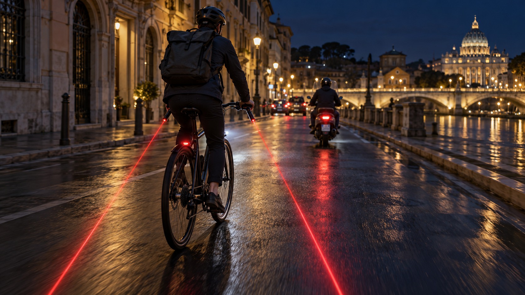
Make the rider visible.
Make the space around them readable.
A rear light marks a point. Could a projected line help other road users read the rider’s surrounding space?
This project explores an additional visibility cue for bicycles and scooters: a compact module at the end of the handlebar, projecting red light onto the road. The question is whether that cue can be understood quickly, without adding distraction.
The projection is a design hypothesis. It does not define a legal passing distance or establish a protected lane.
Night, poor weather and competing lights make visibility a critical research topic.
Explore whether a ground-level cue makes lateral proximity easier to judge.
Integrate into the bar end, preserve the grip and keep daily charging accessible.
ILLUSTRATIVE SCENARIOShop windows, headlights and street lamps compete for attention. Explore whether a simple red line on the road remains recognisable when a car approaches from behind.
Recognition from the driver’s viewpoint; line contrast on asphalt; interpretation during an overtake.
Retain conventional front and rear lights. Evaluate the projection as an additional cue.
The familiar handlebar end becomes the mounting point. Two cylinders and one ball joint turn a visibility idea into a compact product architecture.
A compliant cylindrical plug fits inside an open bar end. Retention, bar diameters and clearance need to be developed together.
A ball-and-socket joint lets the shorter cylinder be aimed downward. Friction and stops must preserve its setting through vibration.
Battery, electronics, laser, refractive optic and USB-C live inside the shorter housing, with access for charging and servicing.
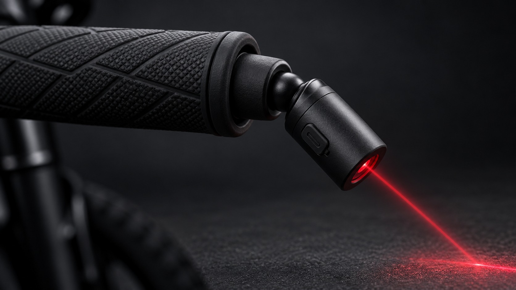
The longer cylinder sits inside the handlebar, like a conventional end plug. A compliant interface must resist pulling, twisting and repeated installation without interfering with the rider’s grip.
To resolve: internal bar diameter, insertion depth, retention method and access to existing controls.
Functional architecture only. Battery capacity, dimensions, laser class, output and runtime remain to be specified and verified.
Explore the geometric relationship before selecting optics. Moving the head changes where the beam meets the ground.
Side-view geometry: reach = height / tan(angle). This does not simulate line width, road slope, steering, lean or optical brightness.
Separate fit, aiming and visibility into testable questions. A credible prototype needs more than a convincing render.
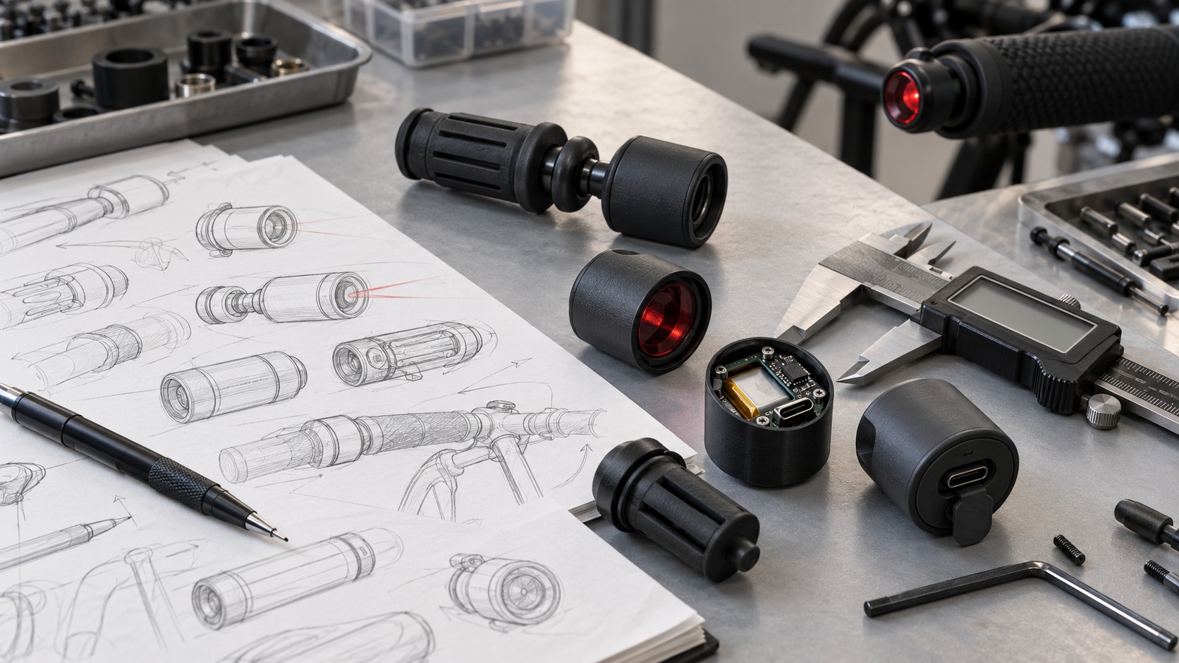
Printed housings and compliant inserts. Check grip clearance, bar compatibility, removal and snagging.
PLANNEDTest joint retention, repeatable adjustment, downward limits and movement under vibration.
PLANNEDMeasure line contrast, operating time, charging behaviour and temperature with selected components.
PLANNEDCompare driver recognition with and without projection on a closed course, across dry and wet surfaces.
PLANNEDOptical safety. Classify the complete laser product and assess direct and reflected exposure, including steering, lean, misalignment and faults. Reference: IEC 60825-1.
Mechanical and electrical behaviour. Verify retention, impact response, water ingress, battery protection, charging and temperature. No protection rating or battery runtime is claimed at this stage.
Rider and driver interpretation. Check distraction, confusion with road markings, visibility under street lighting and performance on wet, uneven and sloping surfaces.
Bicycle and scooter compatibility. Confirm open bar ends, controls, steering clearance and local road-use requirements separately. Existing mirrors and weighted scooter bar ends may require a different mounting solution.
The aim is to understand whether a small, well-integrated object can add a useful cue to night-time mobility.
Current stage: concept exploration. Next: define a compatible mount, select optical and power components, build physical prototypes and collect evidence.
Discuss the project